


Please Leave Us A Message
Privacy statement: Your privacy is very important to Us. Our company promises not to disclose your personal information to any external company with out your explicit permission.

 March 20, 2021
In order to transmit electrical energy, the power system often uses AC voltage and high current loops to send power to the user, and cannot directly measure with the meter. The function of the transformer is to reduce the AC voltage and the large current to the value that can be directly measured by the meter, which is convenient for the meter to measure directly, and provides power for the relay protection and automatic device. Therefore, the Voltage Transformer and the Current Transformer are The power system plays a very important role, and this article describes the difference between the voltage transformer and the current transformer and how to measure the AC line voltage using a voltage transformer.
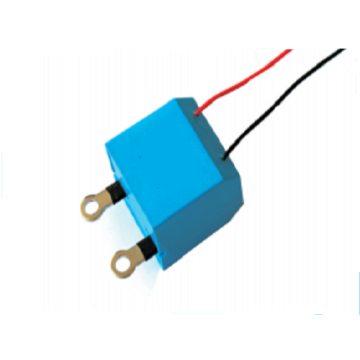
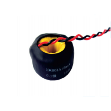
Current transformer function and working principleThe main purpose of the current transformer is to convert the large current in the AC circuit into a certain proportion of small current (5 amps in China) for measurement and relay protection. Everyone should know that in the process of power generation, power transformation, transmission and distribution, the current is often from tens of amps to tens of thousands of amps due to the different electrical equipment, and these circuits may also be accompanied by high voltage. In order to be able to monitor and measure the circuits of these circuits, and to solve the dangers caused by high voltage and high current, current transformers are needed. Some people may have seen a clamp meter for electricians. This is a device for measuring AC current. The "clamp" is a through-current current transformer.
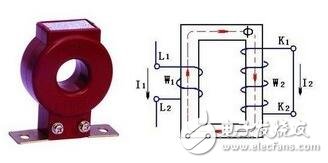
The structure of the current transformer is shown in the figure below, which can be used to expand the range of the AC ammeter. When in use, its primary coil should be connected in series with the load line of the current to be measured, and the secondary coil should be connected in series with the ammeter to form a closed loop, as shown in the circuit diagram on the right in the figure.
The primary coil of the current transformer is wound with a thick wire, and its number of turns is only one or a few turns, so its impedance is extremely small. When the original coil is connected in series to the circuit under test, the voltage drop across it is extremely small. Although the number of turns of the secondary coil is large, under normal conditions, its electromotive force E2 is not high, only about a few volts.
Since I1/I2=Ki (Ki is called the variable current ratio), I1=KiI2
It can be seen that the current through the load is equal to the product of the current measured by the secondary coil and the variable current ratio Ki. If the ammeter is used with a dedicated current transformer, the scale of the ammeter can be marked as the current value in the high current circuit. Current transformer secondary current maximum, usually designed to a standard value of 5A. The current transformers used in different current circuits are different, and the converter ratios are 10/5, 20/5, 30/5, 50/5, 75/5, 100/5, and the like.
For safety reasons, one end of the secondary winding of the current transformer and the iron shell must be grounded.
Current transformer specification model identification method
The current transformer model is composed of 2 to 4 digits of pinyin letters and numbers. Generally, the coil type of the current transformer, the type of insulation, the material of the conductor, and the place of use can be expressed. The number after the horizontal line indicates the voltage level of the insulation structure (level 4). The meaning of the letters in the current transformer model is as follows:
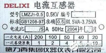
L: in the first position, indicating the current transformer;
D: In the second position, it means single-pass type, and it means differential protection in the last letter of the model (some manufacturers use B or C)
F: In the second place, it means retracement
Q: In the second position, the coil type is indicated, and in the fourth position, the reinforcement type is indicated;
M: in the second position, indicating the bus type;
R: in the second position, indicating the loading type;
A: In the second place, it means through the wall;
C: In the second position, it means porcelain sleeve, and in the third position, it means porcelain insulation;
Z: in the third position, indicating casting insulation;
J: In the third place, it means to increase the capacity enhancement type, and in the fourth place, it means to increase the capacity;
G: In the third place, indicating improvement;
W: In the third place, it means outdoor type;
The role and working principle of voltage transformerThe basic form of the voltage transformer consists of two sets of coils wound with wires and they are inductively coupled together. When an alternating current (having a certain known frequency) flows to one of the coils, an alternating voltage having the same frequency is induced in the other coil, and the magnitude of the induced voltage depends on the two coil coupling and the magnetic flux. The extent of the chain.
The voltage transformer is referred to as PT, and its working principle is very similar to that of the transformer. It is used to change the voltage on the line. When measuring the large voltage of the alternating current, in order to safely measure a transformer connected in parallel between the live line and the ground line (connected to the input end of the transformer), the output of this transformer is connected to the voltmeter, because the number of turns of the input coil is greater than The number of turns of the output coil, so the output voltage is less than the input voltage, the voltage transformer is the step-down transformer.
The role of voltage transformers:
1. Convert the high voltage into a standard secondary voltage of 100V or lower in proportion to the protection, metering, and metering devices.
2. Use voltage transformers to isolate high voltage from electrical workers.
3. When the secondary load impedance decreases, the secondary current increases, so that the primary current automatically increases by one component to satisfy the electromagnetic equilibrium relationship between the secondary sides.
Voltage transformer wiring diagram:
1. Wiring of a single-phase voltage transformer
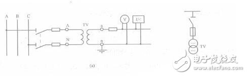
This type of wiring can only measure the line voltage between two phases on a three-phase line, and is used to connect a voltmeter, a frequency meter, and a voltage relay.
2. Two single-phase wiring methods, also called incomplete star connections, can be used to measure three line voltages, and the instruments and relays are connected to the respective line voltages of the three-phase three-wire system. '
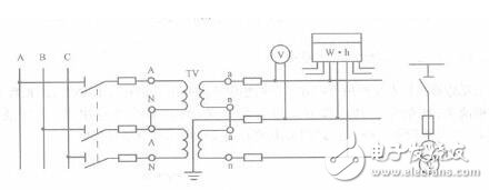
This type of wiring, also known as incomplete star connection, can be used to measure three line voltages for instruments and relays connected to the line voltages of three-phase three-wire circuits.
3. Three single-phase voltage transformers Y. /Y. Wiring
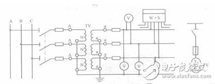
This wiring method can meet the requirements of phase voltage and line voltage for instrument and microcomputer protection devices. In the case of a point grounding of the primary winding, an insulation monitoring voltmeter can also be installed.
4. Three single-phase three-winding voltage transformers or one three-phase five-core three-winding voltage transformer Y. /Y. /
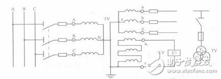
This wiring method is widely used in 10kV neutral point ungrounded systems. It can measure line voltage, phase voltage and can form insulation monitoring device and single phase grounding protection. Connected to Y. The secondary winding of the shape is called the basic secondary winding and is used to connect the instrument, the relay and the insulation monitoring voltmeter; the secondary winding connected to the (open triangle) is called the auxiliary secondary winding and is used to connect the voltage for monitoring the insulation. Relay. When the system is in normal operation, the voltage across the open triangle is close to zero. When the system is grounded, the zero-sequence voltage appears at both ends of the open triangle, so that the voltage relay pulls in and sends a grounding warning signal.
The difference between voltage transformer and current transformer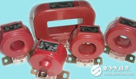
The main difference between a voltage transformer and a current transformer is that the operating state is very different during normal operation.
1) The current transformer can be short-circuited twice, but it must not be opened; the voltage transformer can be opened twice, but it must not be short-circuited;
2) Compared with the load on the secondary side, the primary internal impedance of the voltage transformer is small or negligible, and the voltage transformer can be considered as a voltage source; while the current transformer has a large internal resistance, so that it can be considered It is a current source with an infinite internal resistance.
3) When the voltage transformer works normally, the magnetic flux density is close to the saturation value, and the magnetic flux density decreases when the fault occurs; the magnetic flux density is very low when the current transformer works normally, and the magnetic current becomes very large due to the primary side short-circuit current during the short circuit. The pass density is greatly increased, sometimes even exceeding the saturation value.
Small class of knowledge: How to measure AC line voltage using voltage transformerSingle-phase voltage circuit is measured by voltage transformer: In the AC circuit, the voltage is often measured by a voltage transformer and an AC voltmeter with a range of 100V, which not only expands the meter range, but also is safer. The circuit for measuring single-phase voltage using a voltage transformer is as follows:
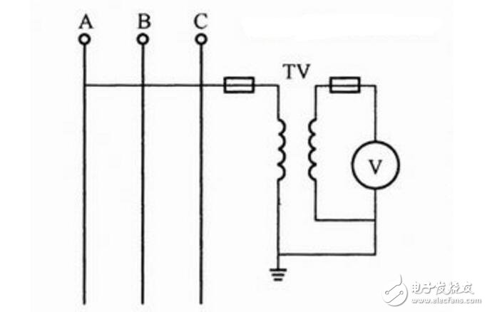
Single-phase voltage circuit measured by voltage transformer
Note when using a voltage transformer:
The voltage transformer does not allow short circuits, so the primary and secondary windings are connected with fuses.
For safety, one end of the secondary winding must be reliably grounded.
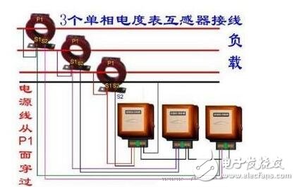
Three-phase line voltage circuit is measured by two single-phase voltage transformers:
Three-phase line voltage circuit measured by two single-phase voltage transformers
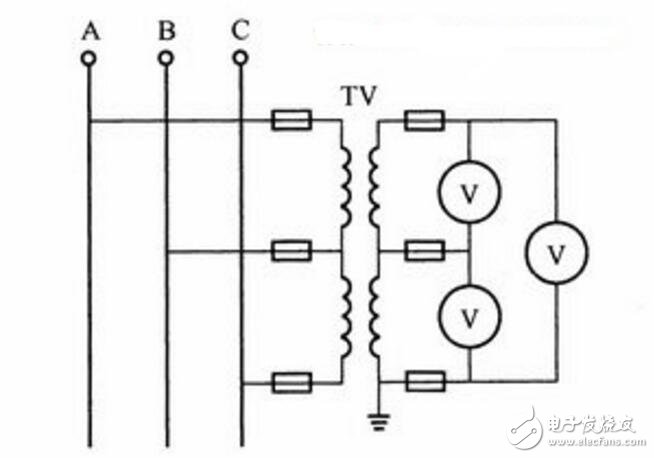
Three-phase line voltage circuit is measured by three-phase voltage transformer:
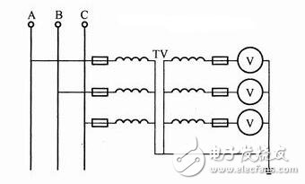
Three-phase line voltage circuit measured by three-phase voltage transformer
The above is the Current transformer function and working principle _ The role and working principle of voltage transformer _ voltage transformer and current mutual we have listed for you. You can submit the following form to obtain more industry information we provide for you.
You can visit our website or contact us, and we will provide the latest consultation and solutions
Send Inquiry
Most Popular
lastest New
Related Products
Send Inquiry
Contact Us

Mobile Site
Privacy statement: Your privacy is very important to Us. Our company promises not to disclose your personal information to any external company with out your explicit permission.
Fill in more information so that we can get in touch with you faster
Privacy statement: Your privacy is very important to Us. Our company promises not to disclose your personal information to any external company with out your explicit permission.